Do you need help with learning Dive Equipment Theory for the PADI IDC or Divemaster course?
Scuba Cylinders
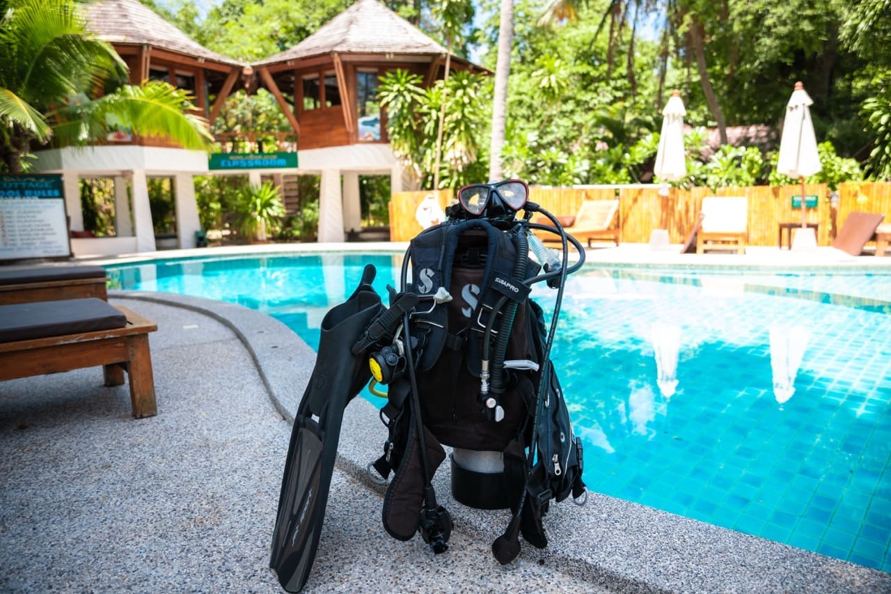
Let’s talk about dive equipment theory. Scuba divers breathe compressed air contained in a cylinder. The typical scuba cylinder, or tank, weighs approximately 14kg when empty and holds 2265litres of compressed air at 204bar. This volume of gas would approximately fill a phone booth and weighs about 3.2kg.
Scuba cylinders are made of either steel or aluminium (aluminum alloy). – dive equipment theory.
Steel:
The first cylinders were made from steel and this material remains popular today.
Steel cylinders are hard and therefore resistant to external corrosion. The strength of the material means than steel tanks typically have thinner walls with larger internal volumes for a given external size. Hence it would be fair to say that steel cylinders hold the same air pressure with thinner walls than aluminium tanks – dive equipment theory
Steel tanks make your dive equipment a bit heavier, they are negatively buoyant even when empty. The advantage of this would be less weight on the weight belt. The highest capacity cylinders are steel, and coupled with the buoyancy characteristics is why tec divers almost always choose steel for their doubles setups.
The primary drawback is that without proper care, they may rust – an oxidation reaction with iron that yields iron oxide. – dive equipment theory
Aluminium:
In dive equipment theory we have found out that aluminium is a softer metal than steel, and so more susceptible to external damage. As it isn’t as strong as steel, the walls of aluminium cylinders must be thicker. This makes this type of cylinder larger and heavier out of the water, yet more positively buoyant in the water.
Aluminium does not tolerate overfilling nearly as well as steel does.
Although aluminium corrodes, as does steel, the aluminum oxide adheres to the metal, creating a barrier that inhibits further corrosion. This means that aluminium tanks are far more forgiving in salt water and are less subject to weakening due to corrosion.
Popular cylinders include the 12litre steel and the 11litre aluminum.
Markings:
If you have a look closely at the top of your scuba tank you will notice a lot of tank markings.
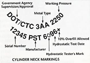
Each of these tank markings in this dive equipment theory have a purpose and are important to determine whether the scuba tank is suitable for you as a diver. The information on the tank should also be referred to when your tank needs re-testing or filling.
Alloy Designation or Metal Type: The 2nd set of characters in the first row denotes the type of metal used in the cylinder. 3AA is the designation for chrome-molybdenum steel. It appears on virtually all steel cylinders in use today. Aluminium cylinders may bear the designation SP6498, E6498 or more typically 3AL.
– dive equipment theory is a must to learn for PADI IDC candidates –
Working Pressure: The third set of characters in the first row indicate the maximum pressure (in pounds per square inch) to which a cylinder may be filled for normal use. A cylinder should not be filled beyond this point. The single exception occurs with steel cylinders that bear a + (plus) sign (discussed later).
Serial Number: The first set of characters in the second row indicates the cylinders unique serial number. The Manufacturer Identification usually follows the serial number and is the second set of characters in the line.
Hydrostatic Test Date: A cylinders initial hydrostatic test date will usually appear as the last or only item in the last row of information originally stamped on the cylinder. Subsequent test dates may appear anywhere on the cylinder’s neck. The test date numbers represent the month and year in which the cylinder was tested and these numbers are separated by the hydrostatic tester’s initials or a special registered symbol.
Over-Pressurization Designation: The last symbol in the line, a plus (+) symbol, indicates that the tank may be overfilled to 10% of its working pressure. This will appear on steel tanks only and is valid for the first hydrostatic test.
“dive equipment theory will help you pass the PADI Divemaster Exam”

Download the full PADI IDC/IE Dive Theory Practice Exams here
Testing Your Dive Equipment
Hydrostatic Tests
Day to day maintenance of a scuba cylinder is simply rinsing, drying and storing after each use. However, it also needs to be protected from damage, to keep moisture from entering it and to have it inspected and tested regularly.
Many countries require periodic pressure testing to determine the structural integrity of a cylinder. The interval between hydrostatic tests varies from three to seven years (every 5 years in the US, every 4 years in the UK).
“How can I prepare for dive equipment theory for the Divemaster and Dive Instructor (IDC) Course”
The test is called hydrostatic testing as it involves water. The cylinder is filled with water and is placed in a water-filled jacket. It is then pressurized to five-thirds of its working pressure i.e. the tester fills the cylinder to greater than its working pressure (or to a test pressure stamped on the cylinders neck). This pressurizing causes the cylinder to expand and displace water into the jacket. The displaced water rises into a collection tube and a reading is able to determine how much the cylinder expanded.
The pressure is then released allowing the metal to contract and although the high pressure may have caused some permanent expansion, this is acceptable if very slight. If the expansion is too high, the metal is too fatigued to use safely. The cylinder will be stamped with the test date and testers identification symbol if the metal has not expanded beyond a reasonable and safe limit.
Visual Inspection
Most of the diving community require a visual inspection annually. It examines a cylinder internally and externally for any signs of damage or corrosion. Using special lights and mirrors, the cylinder interior is checked for corrosion, stress cracks around the neck and other warning signs.
Dive equipment theory for the PADI IE
Rinsing with distilled water and drying with warm air usually removes minor contaminants from the inside of an aluminium cylinder. Minor oxidation in a steel cylinder may be best left in place because the removal process can weaken the cylinder more than the oxidation itself.
If a cylinder has extensive oxidation or deep pitting (oxidation creates a gouge in the metal), it will require sandblasting or tumbling. These methods remove a portion of the cylinder along with the corrosion, so the cylinder will subsequently require pressure testing.
You should test a cylinder ahead of schedule if:
- Loose material can heard rolling around inside.
- Red or greenish material is accumulating on the divers regulator inlet filter.
- The cylinder is filled beyond its working pressure (more than 10%)
- The cylinder has suffered possible impact damage (which requires pressure testing).
- It hasn’t been used in over two years.
If a cylinder is exposed to extreme heat in excess of 82 degrees. This can alter the molecular structure of the metal. This will make it more brittle and less able to withstand constant expansion and contraction. The cylinder with lose its flexibility and rupture when filled. Hence if a tank is exposed to this temperature or above, it will require hydrostatic testing.
This also why a cylinder should never be repainted using a heat painting process because high heat can weaken the cylinder.
Valves
K-Valve: The outside of a valve consists of a simple on/off assembly with a hand turn wheel (knob). You open or close the valve to control the flow of air/gas to or from the cylinder.
J-Valve: Some older cylinder valves may have a reserve mechanism, but these have faded from use. The J-valve got its name from being item number J in one of the first scuba equipment manufacturer catalogues. (The standard non-reserve yoke valve at the time was item K, and is often still referred to as a K-valve) The J-valve predates the submersible pressure gauge.
The J-valve is a spring-loaded mechanism, and was designed as a means to warn the diver has run low on air.

Download the full IDC/IE Dive Theory and PADI Standards Practice Exams here
How to learn dive equipment theory
The way that the J valve works is at the beginning of the dive the reserve valve is closed but it is on a spring set to about 20 to 35 bar, so as long as there is more that 35 bar in the tank the spring is pushed back and air flows. When the tank pressure drops below the spring threshold pressure- the spring has more power than the air pressure and it closes. To release the pressure, the diver would pull on a lever (usually pulling the lever to the “down” position) to release the last 35 bar by opening the reserve valve to finish the dive before the reserve was consumed.
On occasion, divers would inadvertently trigger the mechanism while donning gear or performing a movement underwater and, not realizing that the reserve had already been accessed, could find themselves out of air at depth with no warning whatsoever.
When filling a cylinder equipped with a J-valve, the reserve lever must be in the “down” position.
Yoke System: Cylinder valves use either the yoke system or the DIN system. With the yolk system, the regulator fits down over the valve. It is basically an oval metal loop with a screw opposite the regulator that clamps it to the tank valve.
DIN: Deutsche Industrie Norm. With the DIN system the sealing o-ring mounts (is on) the regulator, which screws into the DIN system. Remember: DIN screws IN!
Advantages of using the DIN system over the yoke system include:
A better seal between the cylinder and regulator valves because the O-ring is actually trapped between the two valves.
The cylinder valve and regulator are secured by threads, and so the connection is much stronger than the yoke screw assembly.
The O-ring is enclosed deep within the cylinder valve and is more stable, and enables the use of much higher air pressures.
Sairee Cottage Diving dive equipment theory
Burst Disks
Burst disks are required by law in many countries. All cylinders have a maximum working pressure beyond which they should not be filled. To reduce the possibility of over pressurizing a cylinder, a burst disk is installed in the cylinders valve.
A burst disk is a thin copper disk held in place by a gasket and vented plug. If the cylinder pressure rises to approximately 140% of the working pressure, the disk ruptures to allow the air to escape through the vented plug.
Not only do burst disks protect against damage that may occur from overfilling, but also from overheating. If a cylinder is at its working pressure in room temperature, and is then placed in a hotter environment (the boot/trunk of a car), the cylinder will then rise above its working pressure. The burst disk will rupture before the pressure can get high enough for the cylinder to explode.
These can weaken over time and need to be replaced regularly by a qualified equipment technician. During the continual filling and emptying of a cylinder, the disk is constantly stressed and the metal weakens. This means that the disk could blow at a pressure far lower than its rated pressure.
Newer burst disks are designed allowing the air to escape in multiple directions. Older disk plugs allow the escaping air to vent directly out (perpendicular to the cylinder valve), which can result in the cylinder spinning, sometimes out of control.
Regulators
There are three basic types of scuba dive equipment, with open circuit being the most commonly used.
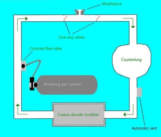
Semi-closed circuit: The diver inhales from a bag or counter-lung, and the exhaled breath cycles through a system that removes waste carbon dioxide and returns it to the counter-lung. It replaces consumed oxygen by employing a slow, steady flow of gas into the counterlung resulting in a slow, small stream of bubbles.
Semi-closed circuit equipment generally supplies one breathing gas such as air or nitrox or trimix. The gas is injected into the loop at a constant rate to replenish oxygen consumed from the loop by the diver. Excess gas must be constantly vented from the loop in small volumes to make space for fresh, oxygen-rich gas. As the oxygen in the vented gas cannot be separated from the inert gas, semi-closed circuit is wasteful of oxygen.
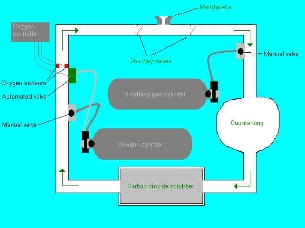
Closed-circuit: The inhaled breath comes from a bag/counter-lung, and when exhaled, is then cycled through a system that removes waste carbon dioxide and replaces the consumed oxygen, then returned to the bag. There are no bubbles.
Open-circuit: When a diver inhales, they breathe in from a compressed gas cylinder. This is known as a demand system. When a diver exhales, the breath vents into the water and bubbles to the surface i.e. exhaled air is released directly into the water. It means that the path of the air from the cylinder terminates when it is exhaled into the water.

Download the full PADI IDC Dive Theory Summaries here
The open circuit consists of two stages, the 1st stage and the 2nd stage. To be able to breathe, air need to be delivered at a pressure that is about the same as the surrounding pressure. This is essentially what an open circuit scuba regulator does.
1st Stage: Has several ports that hoses attach to leading to the 2nd stages and other devices such as the pressure gauge, low pressure inflator and dry suit inflator. It basically functions as a pressure-reduction valve.
The primary function of the first-stage, is to take the high pressure air delivered from the tank and reduce it to an intermediate pressure.

1st stage pressure sensing systems fall into two categories: piston and diaphragm.
In diaphragm first stages, the diaphragm is a flexible cover to the intermediate-pressure chamber. When the diver inhales, the pressure falls in the intermediate-pressure chamber below the desired ambient pressure and the diaphragm collapses inwards pushing against the valve lifter. This opens the valve letting high-pressure gas pass the valve seat into the intermediate-pressure chamber.
When the diver stops inhaling, the pressure in the intermediate-pressure chambers rises and upon reaching intermediate-pressure the diaphragm inflates outwards reducing the force on the valve lifter, letting the spring behind the valve close it ie the tank closes and air no longer flows.
PADI Diving Instructor Course dive equipment theory
Piston type first stages have a simpler design than the diaphragm type. With the piston-type first stage, the piston is rigid and acts directly on the seat of the valve. When the pressure in the intermediate pressure drops, as the diver inhales from the second stage, the piston lifts off the valve seat and slides towards the intermediate pressure chamber. This brings high pressure gas into the intermediate pressure chamber until the pressure in the chamber has risen enough to push the piston back onto the seat and close the valve.
2nd Stage: The second-stage continues the process discussed in above. It takes the intermediate pressure from the first stage and breaks it down to a pressure equal to the surrounding water pressure. The ambient pressure is sensed by a flexible second-stage diaphragm.2nd stages have two basic valve types, downstream and pilot valves.

Downstream valves are the most common. When the diver inhales, the diaphragm pushes against a demand lever connected to a one way valve. This is because when inhaling, the pressure within the 2nd stage is lowered to below ambient water pressure and the water pressure presses in on the diaphragm. This causes the valve to open, supplying the diver with air. As the valve opens with airflow, it is called downstream (the pressure is trying to open the valve). **
When the diver exhales, the pressure in the 2nd stage exceeds ambient water pressure and pushes the diaphragm out allowing the lever to return to its normal position thereby closing the inlet valve. The increased pressure in the 2nd stage opens the exhaust valve allowing exhaled air to leave the 2nd stage.
One advantage with a downstream valve is that if the valve does fail, it almost always fails in the open position. This is called a fail-safe design (discussed more later).
** Contrary to downstream valves upstream valves open against the flow of air (the pressure is trying to close the valve).
With a pilot valve, when you inhale the diaphragm depresses on a lever on a small valve. The small valve releases air pressure (or creates a pressure imbalance) that in turn opens the larger main valve i.e. a smaller valve that opens a larger valve.
Drawbacks to pilot valves second stages include complexity and expense. They also tend to free flow easily, so most have dive/pre-dive switch. The pre-dive setting puts tension on the diaphragm so it doesn’t free flow as easily when it is not in the diver’s mouth.
Remember, pilot valves appear in the 2nd stage only!
Balanced and Unbalanced:
The difference between unbalanced and balanced regulators is to do with a design that offset variations in cylinder pressure.
“In our dive equipment theory lessons during the IDC we focus a lot on Balanced and Unbalanced First Stages”
In an unbalanced regulator/valve, the cylinder pressure presses on the valve and assists opening it. As the air in the cylinder is used up, the pressure lessens and therefore doesn’t assist with opening the valve. This causes a minor variation in performance. Cylinder pressure resists or assists the opening of valves in the first stage.
A balanced valve uses a design that routes high pressure cylinder air around both sides of the valve opening. This cancels out or balances cylinder pressure so that performance stays the same throughout your dive. Cylinder pressure does not influence its operation.

Download the full PADI IDC/IE Standards Practice Exams here
As a result, larger orifices can be used providing more air flow to the diver. This, in turn, makes the regulator breathe easier than a similar though unbalanced design. The greater air flow also makes it easier to supply a second diver who might be breathing from an alternate air source.
Fail-Safe/Free Flow Design:
Fail safe refers to a regulator’s tendency to free-flow because of the use of a downstream valve in the second stage. A downstream valve means that it will tend to open with the flow of air. Therefore, if a problem occurs in the first-stage, the air flow will open the valve allowing air to escape to the second stage. Then, the downstream design of the second-stage valve will also open, causing the regulator to free-flow. This is a vital safety feature.
dive equipment theory fail safe is part part of the PADI IE Exam
The primary advantage of the fail-safe design of regulators is that in the event of a malfunction, air is still delivered to the diver. Although the air flow is continuous, it’s a situation the diver can deal with while ascending to the surface. Never continue a dive with a free-flowing regulator even if the air flow is “manageable!”
Environmental Sealing:
An environmental seal operates by not allowing water to directly contact the first-stage piston or diaphragm. It acts instead on a silicone or alcohol based fluid that seal inside a watertight pressure-sensitive barrier and transmits the pressure to the piston or diaphragm.
It prevents salt, sediment and other contaminants from entering the first stage, and so reducing internal corrosion or contaminant build up. It also helps isolate the valve mechanism from freezing temperatures, which is important for cold-water environments, where excessively low temperatures may cause the first stage mechanism to malfunction by freezing.
Dive Computers
Proper procedures for using dive computers include:
Each diver should have their own personal computer and not share with their dive buddy.
It is important to follow recommendation that apply to dive tables and to remember that the dive computer uses the same type of model as a dive table. It is also important to follow manufacturer recommendations when using a dive computer.
Depth Gauges
There are several different types of depth gauges including capillary, open bourdon tube, oil-filled, diaphragm and digital.
In dive equipment theory a capillary depth gauge works by using Boyle’s Law (Boyle’s law describes the inversely proportional relationship between the absolute pressure and volume of a gas, if the temperature is kept constant within a closed system). It is a small diameter, clear, empty plastic tube wrapped around a circular dial. It is open at one end to allow water to enter and closed at the other. As a diver descends, the tube fills with water as the air compress which moves the dial.
In accordance with Boyle’s Law, the internal air space will fill with water in a predictable manner — half the original volume at 10 meters, one third at 20m, one fourth at 30m, etc. By marking off where the water column will be at various depths, a crude but highly accurate gauge can be constructed with no moving parts.
In practice, however, capillary gauges are plagued by problems such as difficulty in seeing the rising water column, increasingly small increments of depths beyond 20m, and air bubbles getting into the tube, making it difficult to read accurately deeper than 10m. For these reasons capillary gauges are rarely used as the sole means of determining a diver’s depth. They are most commonly used as backup devices in shallow water. They are reliable and inexpensive.
It is important to note that the accuracy of capillary gauges becomes an issue when diving at altitude. The capillary gauge will read deeper than the actual depth. A diver at an altitude of 300 meters using a capillary depth gauge indicates a depth of 14 meters for example. However, if the linear distance was measured to the surface, the diver would actually be less than 14 meters below the surface. (see objective 3.14 of the Diving Knowledge Workbook). This is because a closed air space will fill with water in accordance to the relative atmospheres it is exposed to. In essence, it will show a relationship of atmospheres rather than indicate an actual ambient pressure and is why diving at altitude requires special procedures and training.
An open bourdon tube is among the most common pressure-sensing mechanisms. It contains a spiral shaped tube, usually made from copper. Water enters the tub end and when the pressure inside the tube becomes greater than the ambient pressure, the tube tends to straighten. The tube in turn is connected to a gauge needle, which moves with the increasing or decreasing pressure. At altitude, it will read shallower than the actual depth.
At Sairee Cottage Diving IDC we have extra PADI IDC preparation day’s to learn: dive equipment theory
The oil-filled gauge also uses a bourdon tube design but here using a sealed tube in an oil-filled housing. The increasing or decreasing pressure is transmitted though the oil and causes the tube to coil more tightly/or loosen. Again this in turn moves the depth gauge needle.
Diaphragm gauges are not as common as others. They function by connecting a flexible diaphragm to a series of levers and gears that move the display needle.
A digital gauge is an electronic gauge that reads depth via a traducer. It will vary the electricity it transmits depending on the pressure exerted on it. It goes on to provide a digital display. The digital gauge offers the highest degree of accuracy.
PRESSURE GAUGES work on the same principle as bourdon tube gauges. The high pressure from the cylinder enters a c-shaped or spiral tube and causes it to straighten somewhat with pressure change, which results in the SPG needle reading the pressure.
By carrying gauges in a wrist mounted fashion, a diver is more streamlined, especially in overhead environments. The console combines several instruments into one package on the SPG or may integrate several instruments into one such as a pressure integrated dive computer. This speeds up dive preparation and doesn’t involve strapping on dive gauges.
Enriched Air Considerations
The main concern with using enriched air, is that as the oxygen content rises, substances combust or burn more readily. This means that materials such as neoprene rubber, lubricants such as silicone grease, and contaminants including dirt particles, could pose a hazard with using enriched air. The dive industry consider this a problem is using more than 40% oxygen and require that equipment is oxygen clean when using enriched air at this blend.
- Enriched air cylinders require distinct markings – labels and tags stating:
- The Oxygen content
- The fill date
- Analyzers name
- Divers name
- Maximum depth which the blend can be used.
Also requires visual inspection sticker stating that it has been specifically serviced for use with enriched air. The diver who will use the tank must always personally analyze the contents of an enriched air cylinder.
We hope that this dive equipment theory helped you in passing the PADI IDC Course, PADI Divemaster Course or PADI IE.